 How-to
7 Marine Solar System Wiring Best Practices for Reliable Off-Grid Power
Last Updated: October 26, 2026
Quick Summary
Marine solar system wiring requires marine-grade tinned copper wire, proper sizing to limit voltage drop to 3-5%, and protected routing through conduit to prevent corrosion, UV damage, and fire risk in saltwater environments. Overcurrent protection, grounding, and bonding are essential to prevent equipment failure and galvanic corrosion.
- Use marine-grade tinned copper wire rated to UL 1426 standard for UV exposure, heat, moisture, and salt spray.
- Size wire to keep voltage drop between 3-5% on array-to-controller runs using the VD formula or online calculator.
- Install DC-rated breakers within 18 inches of the battery and at the solar array to protect against overcurrent and shorts.
- Route all wiring through protective conduit away from chafe points, UV exposure, and high-heat areas.
- Bond all metal components to a common bonding bus with tinned copper wire sized equal to the largest current-carrying wire.
Table of Contents
- Why Marine Solar System Wiring Demands Special Attention
- Understanding Marine Solar Panel Wiring Diagram Fundamentals
- Sizing Wire Correctly: Using a Boat Solar Wire Size Calculator
- Marine Solar Panel Series vs Parallel: Which Configuration Wins
- Marine Solar Fuse and Breaker Sizing for Safe Operation
- Grounding, Bonding, and Galvanic Corrosion Prevention
- Cable Routing, Connectors, and Commissioning Your Marine Solar System Wiring
- Getting Your System Installed and Commissioned with Expert Support
- Frequently Asked Questions
Why Marine Solar System Wiring Demands Special Attention
Salt water, UV exposure, vibration, and temperature swings make standard electrical practices fail. A marine solar system wiring setup that works on land will corrode, short, or catch fire on a boat.
This is where marine solar system wiring best practices become non-negotiable. Cutting corners leads to dead batteries, blown equipment, and expensive repairs in remote locations.
At Victron Guy, we help customers design systems that stay reliable year after year.
Understanding Marine Solar Panel Wiring Diagram Fundamentals
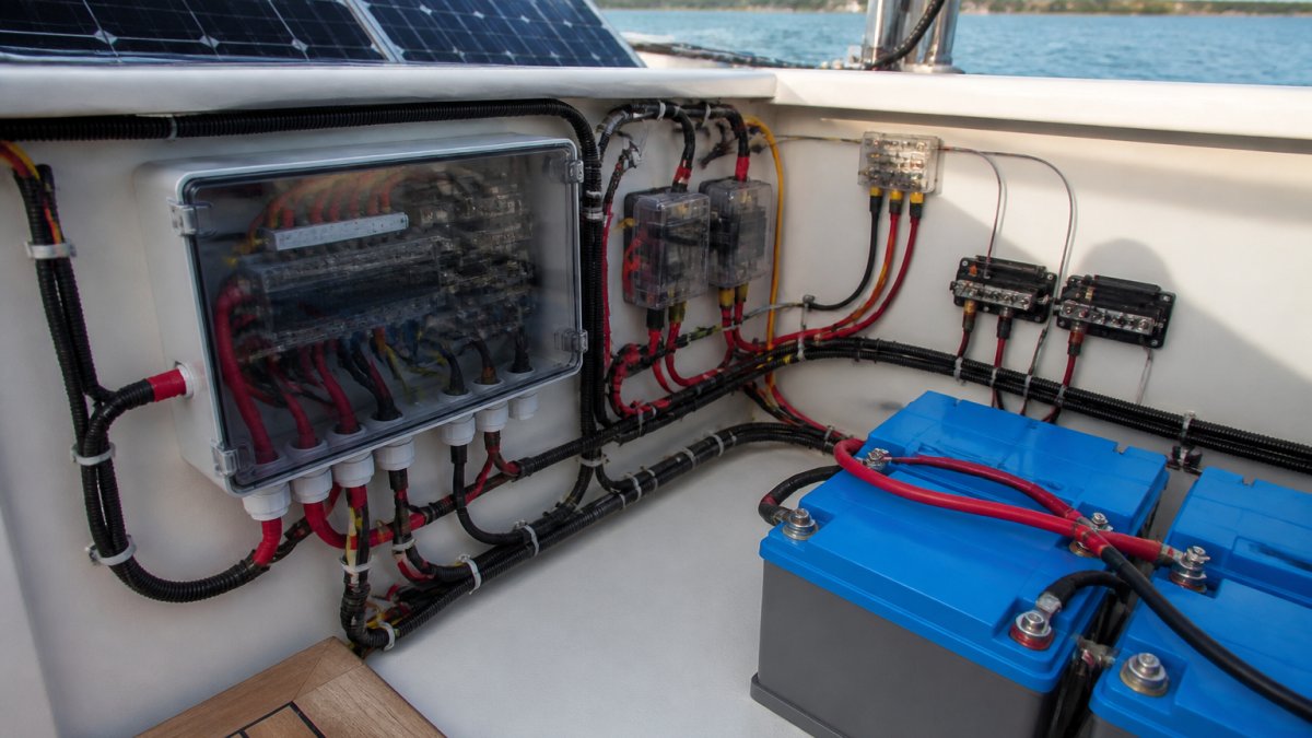
A marine solar system wiring diagram shows how three components connect: solar panels, a charge controller, and a battery bank. Current flows from the panels through the controller, which regulates voltage and amperage before sending power to the batteries. If any connection is undersized, poorly insulated, or corroded, the entire system suffers.
The diagram also shows protection placement: fuses or breakers between panels and controller, and between controller and battery. Grounding and bonding run separately to prevent galvanic corrosion. Every wire must be marine-grade tinned copper, every connection sealed.
Panel-to-Controller Connections
The wire run from your solar array to the charge controller carries DC current at high voltage and generates the most heat. Undersized wire causes voltage drop that reduces charging efficiency, plus heat that can melt insulation and start fires.
Use marine-grade tinned copper wire rated for UV exposure. Standard automotive wire will fail within months on deck.
Run this wire through protective conduit or cable trays, never exposed to direct sun or chafe points.
Controller-to-Battery Routing
The wire from your charge controller to the battery bank carries lower voltage but very high amperage, especially during bulk charging.
Size this wire conservatively, one gauge larger than you think you need.
Seal all connections with heat-shrink tubing rated for marine use. The West Marine marine-grade adhesive heat shrink creates a waterproof barrier that prevents corrosion at the connection point, the most vulnerable spot in any marine electrical system.
Sizing Wire Correctly: Using a Boat Solar Wire Size Calculator
Wire gauge determines how much current flows with acceptable voltage drop. Too small loses power as heat; too large wastes money and adds weight.
Most boat solar systems use 10, 8, or 6 AWG wire for main runs; smaller systems use 12 AWG, larger ones 4 AWG or bigger. The exact size depends on current, run length, and acceptable voltage drop.
The 3-5% Voltage Drop Rule
Voltage drop is the loss of electrical potential across a length of wire.
The marine solar system wiring industry standard is 3% to 5% voltage drop on the array-to-controller run, with some designers aiming for 3% on the battery-to-load circuit. Longer runs and higher current demand larger wire.
Calculate voltage drop with VD = (2 × L × I × R) / 1000, where L is one-way distance in feet, I is current in amps, and R is resistance per 1,000 feet from wire charts.
Worked Example: Sizing for a 400W Array
Imagine a 400W array wired to a 48V charge controller, producing roughly 8-10 amps at full sun over a 60-foot run.
Using a wire sizing calculator:
- 10 AWG wire at 60 feet with 8 amps = 4.2% voltage drop (acceptable)
- 12 AWG wire at 60 feet with 8 amps = 6.7% voltage drop (too high)
So 10 AWG is the minimum; specify marine-grade tinned 10 AWG. A 600W array producing 12 amps would step up to 8 AWG.
Longer runs and higher currents demand thicker wire: a 100-foot run at 8 amps requires 8 AWG instead of 10 AWG. Plan your layout carefully, since every extra foot adds cost and complexity.
Marine Solar Panel Series vs Parallel: Which Configuration Wins
How you wire your panels together affects voltage and current. The right choice depends on your controller, battery voltage, and array size.
Series wiring connects panels end-to-end, adding voltages. Two 24V panels in series produce 48V while current stays the same. Lower current means thinner wire and smaller breakers, which is why large marine systems often use series strings.
Parallel wiring connects panels side-by-side, keeping voltage the same but adding current. Two 24V panels in parallel still produce 24V but double the current.
For marine solar system wiring best practices, series wiring wins for most boats: higher voltage means lower current and less resistive loss in long runs. You can reference a DIY van solar wiring guide to understand how parallel and series principles apply across different systems.
If your battery bank is 12V or 24V, you're limited to parallel or a series-parallel hybrid: two strings in series, then connected in parallel, balancing voltage and current. Use a combiner box with individual breakers per string to isolate faults.
Marine Solar Fuse and Breaker Sizing for Safe Operation
Overcurrent protection prevents fires and equipment damage. A fuse or breaker rated too high won't protect anything; rated too low, it trips constantly. The correct rating depends on the maximum current the wire or equipment can safely handle.
Overcurrent Protection Placement
Place a breaker or fuse between the solar array and the charge controller to protect the controller from array short-circuits.
Never install protection on the load side of the battery (between battery and inverter).
For a marine solar system wiring setup, use DC-rated breakers, not AC breakers. The Blue Sea Systems marine circuit breaker standards specify trip-free design: the breaker cannot be held in the ON position during a fault.
Calculating Breaker and Fuse Ratings
Breaker and fuse ratings are based on the maximum continuous current the circuit carries. For a solar array-to-controller circuit:
- Calculate the maximum short-circuit current (Isc) of your array. This is listed on the panel spec sheet.
- Round up to the next standard breaker size.
- Example: A 400W array with Isc of 10 amps gets a 15-amp breaker.
For a controller-to-battery circuit:
- Use the controller's maximum output current rating.
- Example: A 100-amp controller gets a 100-amp breaker.
Always use the next standard breaker size up if your calculated current falls between standard sizes. A 12-amp circuit gets a 15-amp breaker, not a 10-amp. This prevents nuisance tripping during normal operation.
Grounding, Bonding, and Galvanic Corrosion Prevention
Saltwater is conductive. Different metals immersed in it create galvanic cells, tiny batteries that corrode the more reactive metal.
Bonding connects all metal components to a common reference point (the boat's bonding bus or grounding plate).
Run a bonding wire from the solar array frame to the bonding bus, and a grounding wire from the battery bank's negative terminal to the bonding bus.
Use marine-grade tinned copper for all bonding wires. Size bonding conductors at least as large as the largest current-carrying wire in the circuit.
Cable Routing, Connectors, and Commissioning Your Marine Solar System Wiring
How you physically install the wires matters as much as the electrical design. Poor routing leads to chafe, UV damage, and water intrusion. Poor connectors cause resistance, heat, and corrosion.
Protected Routing and Splices
Run all wiring through protective conduit or cable trays. Bare wire on deck gets destroyed by UV, salt spray, and physical chafe within months.
Minimize splices; every splice is a failure point. If you must splice, use marine-grade crimped connectors with heat-shrink tubing. Never use twist-on connectors (wire nuts) on a boat.
Route wiring away from high-heat areas like engine compartments. Keep positive and negative wires separated by at least 12 inches to prevent accidental shorts.
Connector Selection and Crimping
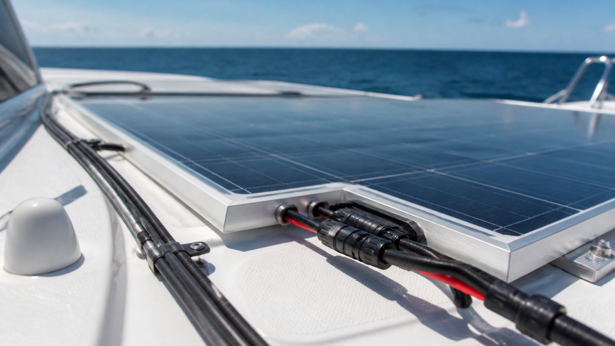
Use MC4 connectors for panel-to-array connections. These are the marine solar system wiring standard, waterproof, UV-resistant, and self-locking. They require a specific crimping tool, but the investment pays off in reliability.
For battery connections, use marine-grade lugs crimped to the wire and bolted to the battery terminals. Never solder battery connections, the heat can damage the battery case.
Use a quality crimping tool. Cheap crimpers produce weak connections that fail under load. A proper marine-grade crimper costs 50-100 dollars but ensures reliable connections.
Pre-Connection Testing and Fault Diagnosis
Before connecting anything to the battery, test the entire system.
Measure voltage at the array terminals in sunlight. A 48V array should read close to 48V. If it reads significantly lower, you have a wiring problem or a panel failure.
Connect the controller to the battery with the array disconnected. Learn how battery monitoring integrates with your wiring setup to track system performance during commissioning.
Monitor the charging current. If it's much lower than expected, you have voltage drop or a panel problem.
| Step | What to Check | Expected Result |
|---|---|---|
| Before connection | Wire continuity, no shorts, controller settings | All wires connected, no beeps between + and - |
| Array test | Voltage at array terminals in sun | Close to rated array voltage |
| Controller input test | Voltage at controller terminals | Matches array voltage (within 2V) |
| Battery connection | Charge controller powers up | No error codes, correct battery voltage displayed |
| Charging test | Current flowing to battery | Expected current for array size and sun angle |
Getting Your System Installed and Commissioned with Expert Support
Marine solar system wiring is technical work, and mistakes are expensive. If you're confident in your electrical skills and have the right tools, DIY installation is possible.
Victron Guy provides expert technical support via phone, text, email, and in-person to help you design and commission your system.
Free shipping on all Victron products makes it easy to get everything you need. Sales tax is free (excluding California).
Getting your marine solar system wired correctly is the foundation of reliable off-grid power.
Frequently Asked Questions
How do you size wire for a boat solar system without over-engineering?
Use the 3-5% voltage drop rule as your guide. Calculate the current your panels produce (watts ÷ voltage), then select wire gauge so voltage drop stays within that range. For example, a 400W array at 48V produces roughly 8.3A. Running 50 feet to your controller at 5% drop requires 10 AWG marine-rated wire. A boat solar wire size calculator simplifies this; you input array size, voltage, cable length, and it returns the minimum gauge. Always round up one size for safety margin.
Should boat solar panels be wired in series or parallel?
Series wiring increases voltage (good for long cable runs and smaller wire gauges); parallel wiring increases current (simpler wiring but demands heavier cable). Most cruisers choose series for panels on deck because it cuts voltage drop and lets you use thinner, cheaper cable. Parallel works better for small arrays very close to the controller. Your charge controller voltage rating (12V, 24V, or 48V) usually decides this. Victron SmartSolar controllers handle both configurations.
What electrical standards apply to marine solar wiring?
Marine systems must meet ABYC (American Boat and Yacht Council) standards for DC wiring. Key rules: use tinned copper marine-rated wire (UL 1426), size all overcurrent protection within 18 inches of the source, ground all negative conductors to the boat's bonding system, and use waterproof connectors rated IP67 or better. Blue Sea Systems circuit breakers and Ancor tinned wire are ABYC-compliant choices. These standards prevent electrical fires and corrosion in the harsh saltwater environment.
Where should fuses and disconnects go in a marine solar system?
Install a disconnect switch and overcurrent protection (breaker or fuse) within 18 inches of the positive terminal on the solar array output, before the charge controller. A second breaker protects the controller-to-battery run. This placement stops fault current before it reaches sensitive equipment. Blue Sea Systems circuit breakers are trip-free (cannot be held in the ON position during a fault) and meet ABYC requirements. Proper sizing prevents nuisance tripping while protecting against shorts.