 ultimate-guide
DIY Van Solar System Wiring Guide (2026)
Table of Contents
- Essential Tools and Safety for DIY Van Solar System Wiring
- Van Solar Wire Gauge Chart: Choosing the Right Wire Size
- Series vs Parallel Solar Wiring: Which Configuration for Your Van?
- Best Fuses for Van Solar Systems: Protection and Placement
- Step-by-Step Wiring for Your DIY Van Solar System
- Grounding and Bonding for Van Solar Systems
- Conclusion
- Frequently Asked Questions
Last Updated: September 24, 2026
Essential Tools and Safety for DIY Van Solar System Wiring
A successful DIY van solar system wiring guide starts with the right tools and a healthy respect for DC power. Unlike household AC, a 12V or 24V battery bank can push hundreds of amps through a dead short, enough to weld metal and start a fire. At Victron Guy, we've walked countless van builders through their first install, and the failures almost always trace back to skipped safety steps, not bad components.
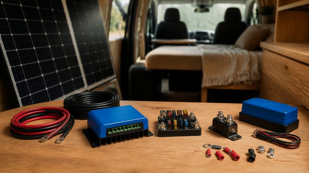
Gather these before you cut a single cable:
- Multimeter with a DC clamp for reading amperage and a continuity test mode
- Crimping tool sized for your lugs (a hammer crimper works, a hydraulic one works better)
- Wire cutters rated for the gauge you're running, plus a cable stripper
- Heat gun and heat shrink to seal every connection
- Torque wrench for battery and busbar terminals
- Insulated gloves and safety glasses for every live-circuit moment
Van Solar Wire Gauge Chart: Choosing the Right Wire Size
Wire gauge is determined by three things: amperage, round-trip distance, and acceptable voltage drop. Undersized cable wastes power as heat and can starve your charge controller. The industry target is keeping voltage drop under 3% for critical runs.
| Circuit | Typical Amperage | Round-Trip Distance | Recommended AWG |
|---|---|---|---|
| Solar array to controller | 10-20A | Up to 20 ft | 10 AWG |
| Solar array to controller | 10-20A | 20-40 ft | 8 AWG |
| Controller to battery | 30-60A | Up to 10 ft | 6 AWG |
| Inverter to battery | 100-200A | Up to 6 ft | 2/0 AWG |
| Battery to busbar | 200A+ | Under 3 ft | 4/0 AWG |
Series vs Parallel Solar Wiring: Which Configuration for Your Van?
Series wiring connects panels positive-to-negative, adding voltage while amperage stays constant. Parallel wiring connects positive-to-positive and negative-to-negative, adding amperage while voltage stays constant. The right choice depends on your charge controller type and roof layout.
Best Fuses for Van Solar Systems: Protection and Placement
Every positive conductor in a van solar system needs overcurrent protection, and it must sit as close to the power source as practical. This is the single most skipped step in amateur installs, and it's the one that turns a minor fault into a fire.
Match the fuse type to the circuit:
- Solar array: inline fuse or DC-rated breaker sized to the panel's maximum current, placed near the controller
- Controller to battery: DC breaker or Class T fuse rated above the controller's output but below the cable's ampacity
- Inverter feed: Class T fuse, because a large inverter can deliver a surge that slower fuses won't clear
- Battery bank main: a high-amperage fuse or breaker on the positive terminal
Step-by-Step Wiring for Your DIY Van Solar System
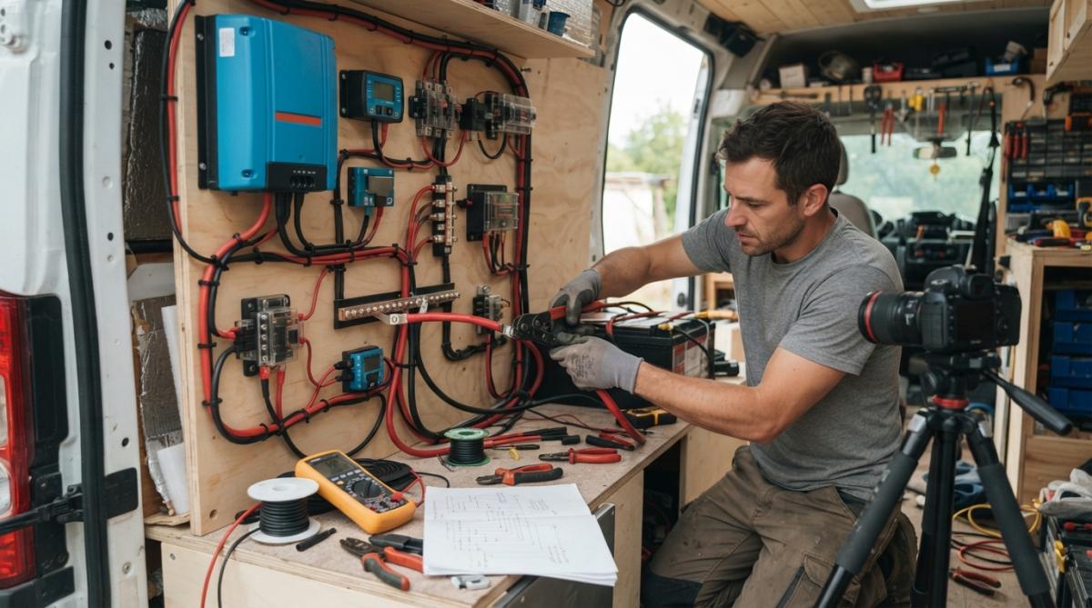
Follow this sequence to build a safe, working system. Work with the battery disconnected until the final step. The order matters: every stage is verified before the next one is energized, so a mistake never has a chance to become a fire.
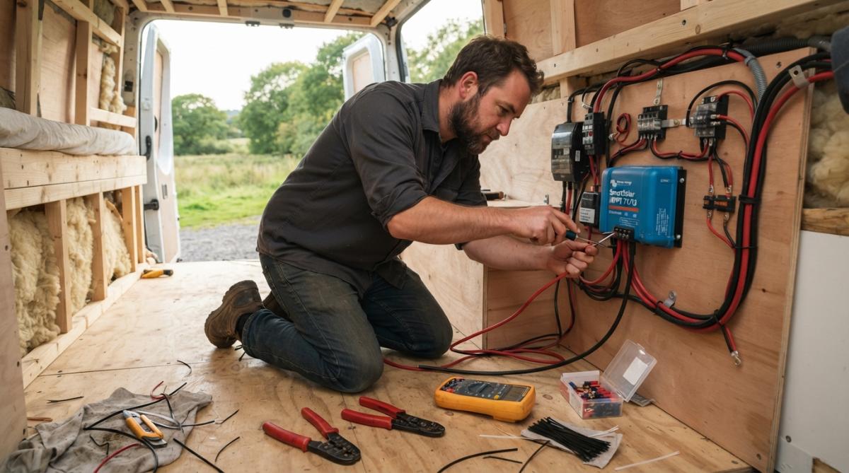
Stage 1, Mount and Prep (Battery Still Disconnected)
- Mount the panels and run cables to the roof entry point. Use a cable gland or a sealed roof box to keep water out of the penetration. Leave a drip loop so water sheds away from the entry, not into it.
- Label both ends of every cable before you pull it. Tag each conductor with its source and destination (for example, "PV+" and "PV-"). This single habit prevents the most common DIY error, reversing polarity at the controller.
- Wire the array in series or parallel per your design. Confirm polarity with a multimeter at the array's home-run leads before connecting anything downstream.
Stage 2, Low-Voltage Connections
- Connect the array to the charge controller through an inline fuse or DC breaker. Verify the controller's maximum PV input voltage exceeds your array's open-circuit voltage (Voc), and remember that Voc rises in cold weather, so size for the coldest morning your build will see, not the label on the panel.
- Connect the controller to the battery bank through a DC breaker, observing correct polarity. Most controllers want the battery connected before the array so they can sense system voltage and auto-detect 12V vs 24V. Check your controller's manual, the sequence differs by brand.
- Install the busbar for positive and negative distribution. Torque every lug to the terminal manufacturer's spec. A common range for M8 battery and busbar studs is roughly 8-10 N·m (about 70-90 in-lb), but always follow the component's own datasheet rather than a generic number.
Stage 3, High-Current and AC
- Wire the inverter directly to the battery through a Class T fuse, keeping the run as short as physically possible. Long inverter feeds are where voltage drop and heat build up fastest.
- Ground and bond the system to the van chassis (see the grounding section below), then reconnect the battery negative last.
Stage 4, Commissioning
- Power up in stages and check voltages at each point with your multimeter before switching on any loads. Confirm array voltage at the controller input, battery voltage at the controller output, and busbar voltage under no load.
- Connect a small test load, a 12V light or a phone charger, before you run the inverter. If the controller shows incoming solar voltage and the battery accepts charge, the DC side is working.
- Test the inverter with a resistive load first (a lamp or a small heater), then a reactive load (a laptop power supply or a fan). If a breaker trips, stop and re-check polarity and torque before resetting it.
Expected Result: The controller shows incoming solar voltage, the battery accepts charge, and the inverter powers a test load without tripping protection. If any stage reads zero volts or a breaker trips repeatedly, disconnect the battery and re-verify polarity and crimp quality before continuing.
Grounding and Bonding for Van Solar Systems
Grounding ties your system's negative return to the van chassis, while bonding connects metal enclosures and frames to that same reference. Together they give fault current a safe path and reduce the risk of shock and stray current. Most DIY guides stop there. What they skip is the compliance layer, and that layer is what separates a build that passes an insurance inspection from one that gets flagged.
The Compliance Angle Most Guides Miss
There is no single federal code written specifically for van electrical systems, but two established standards are commonly referenced by insurers, marine surveyors, and professional upfitters:
- ABYC standards (American Boat and Yacht Council) govern DC grounding and bonding in marine and mobile environments. Because van systems share the marine world's 12V/24V DC architecture and vibration exposure, many builders and inspectors treat ABYC guidance as the practical benchmark.
- NFPA 70, the National Electrical Code, sets the baseline for overcurrent protection, conductor sizing, and grounding that most insurers reference even for vehicles. The NFPA 70 National Electrical Code is the document to cite when an adjuster asks how your system was protected.
How to Ground and Bond Correctly
Connect the battery negative, the inverter chassis, the charge controller case, and the panel frames to a common ground point on the chassis. Scrape paint to bare metal, use a star washer to bite through any remaining coating, and coat the finished connection with a corrosion inhibitor. A shunt on the negative cable lets your battery monitor track state of charge accurately without disturbing the ground path.
Conclusion
Wiring a van solar system rewards patience and punishes shortcuts. Get the wire gauge right, protect every positive conductor, and ground the whole system to the chassis before you power anything up. If you'd rather not guess, Victron Guy carries a full catalog of Victron Energy charge controllers, inverters, batteries, and monitoring systems, and as an authorized dealer we back every order with free shipping and real technical support by phone, text, email, or in person.
Frequently Asked Questions
What gauge wire do I need for a van solar system?
Wire gauge depends on current and distance. Use 10 AWG for up to 30 amps, 8 AWG for 40-55 amps, and 6 AWG for 60-80 amps. For long runs, increase gauge. Always consult a van solar wire gauge chart to prevent voltage drop and overheating. Proper sizing ensures efficiency and safety in your DIY van solar system wiring guide.
Do I need a fuse between my solar panels and charge controller?
Yes, a fuse or circuit breaker between panels and charge controller protects against overcurrent. Use an inline fuse rated for 1.25 times the panel's short-circuit current. For example, if your panels produce 10A, use a 15A fuse. This is a critical safety measure in any DIY van solar system wiring guide.
How do I connect solar panels to a battery in a van?
Connect panels to a charge controller, then to the battery. Use proper wire gauge and fuses. For series vs parallel solar wiring, series increases voltage, parallel increases current. Follow the controller's manual. Always disconnect panels before working on wiring. This step-by-step approach ensures a safe DIY van solar system wiring guide.
Is it better to wire solar panels in series or parallel for a van?
Series wiring is better for long distances and MPPT controllers, as it reduces voltage drop. Parallel wiring is better for partial shading. For vans, series is often preferred for efficiency. Consider your controller type and shading. This decision is key in your DIY van solar system wiring guide.
What safety standards should I follow for van electrical installations?
Follow NFPA 70 (NEC) and ABYC standards for marine and RV electrical systems. Use proper fuses, circuit breakers, and grounding. Ensure all connections are secure and insulated. For insurance compliance, document your installation. These standards ensure a safe DIY van solar system wiring guide.
How do I ground a solar system in a campervan?
Ground the negative battery terminal to the van chassis using a heavy-gauge wire. Ground solar panel frames and charge controller per manufacturer instructions. Use a busbar for multiple grounds. Proper grounding prevents shocks and protects equipment. This is essential in any DIY van solar system wiring guide.